Interference of Light
Interference of light refers to the phenomenon where two or more light waves interact with each other, resulting in a new wave pattern.
Huygens' Wave Theory
Huygens' wave theory states that every point on a wavefront can be considered as a secondary wave source, and the new wavefront is the envelope of all these secondary wavelets.
Superposition Principle
The superposition principle states that when two or more waves meet at a point, the displacement at that point is the vector sum of the displacements of the individual waves.
The mathematical equation representing the superposition principle is given by:
$$Y = y_1 + y_2$$where y1 & y2 are displacement of individual waves and Y is the displacement of resultant wave.
Coherence
Inorder to form an interference pattern, light waves which causing it should be coherent. The conditions of coherence are,- The waves should have same wavelength or frequency
- The waves should have nearly same amplitude
- Two waves should have zero or a constant phase difference
Path difference and Phase difference
Path difference
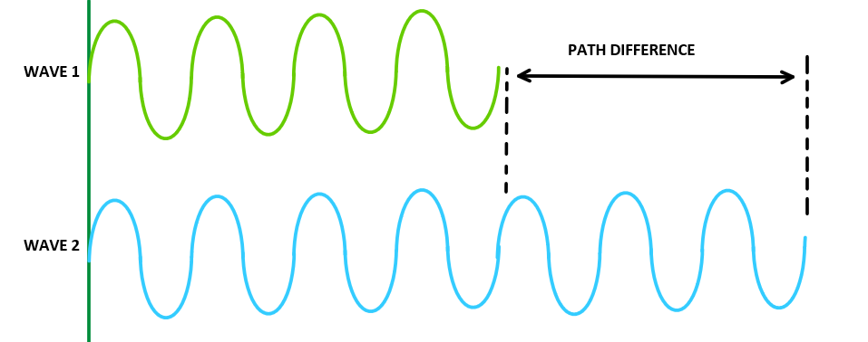
The path difference between two waves is the difference in the distance traveled by the two waves from their point of origin to a given point in space.
Phase difference
The phase difference between two waves refers to the difference in the position of the oscillations of the two waves at a given point in time. It is measured in degrees or radians.
If the oscillations of two waves are in phase, they will have a phase difference of 0 degrees or 0 radians. If the oscillations of two waves are exactly out of phase, they will have a phase difference of 180 degrees or pi radians.
Relation between path difference and phase difference
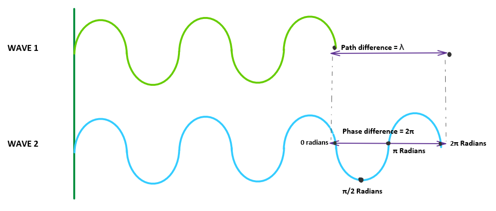
\( 2\pi \) phase difference between two waves refers to path difference of \( \lambda \) ( one wavelength ). In other hand, path difference (\(\Delta x \)) can be related to phase difference \( \Delta \phi \) as,
$$\boxed{ \Delta \phi = \frac{2 \pi}{\lambda}\;\Delta x} $$Types of interference
Constructive Interference
If two waves interfere and gives a maximum, this type of interference is called constructive interference. The condition for maximum is that path difference between them should be an integer multiple of wavelength of light.Condition for maximum
$$\boxed{Path\;difference=n \lambda }$$ In term of phase difference, $$Phase\;difference=2n\pi $$ where n = 1,2,3... and \( \lambda \) is the wavelength of light.Destructive Interference
If two waves interfere and gives a minimum or darkness, this type of interference is called destructive interference. The condition for minimum is that path difference between them should be half integer multiple of wavelength of light.Condition for minimum
$$\boxed{ Path\;difference=(2n-1) \frac{\lambda}{2} }$$ In term of phase difference, $$ Phase\;difference=(2n-1){\pi} $$ where n = 1,2,3... and \( \lambda \) is the wavelength of light.Optical path length
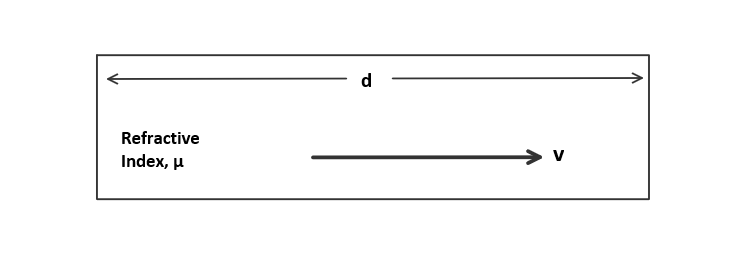
Optical path length (OPL) is a term used in optics to describe the distance that a light beam travels through a medium. It is the product of the physical distance traveled by the light (\(d\)) and the refractive index of the medium ( \( \mu \))through which the light is traveling.
Path difference due to dissimilar reflection
When a light wave gets reflected from a denser boundary an additional path difference of λ/2 will be assigned to it.In other hand, reflection on a denser medium reverses the phase of wave by π radians.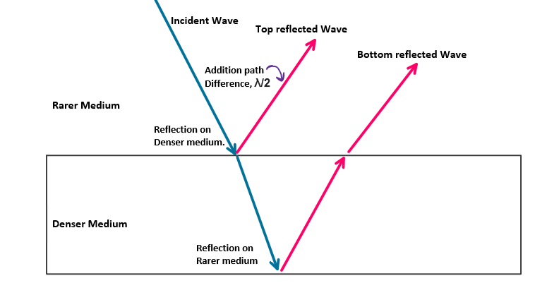
Thin Film Interference
Thin film interference occurs when light reflects off the top and bottom surfaces of a thin film, resulting in constructive and destructive interference.
Light waves gets reflected from top and bottom surfaces. These reflected waves interferes and give alternative dark and bright bands above the film.
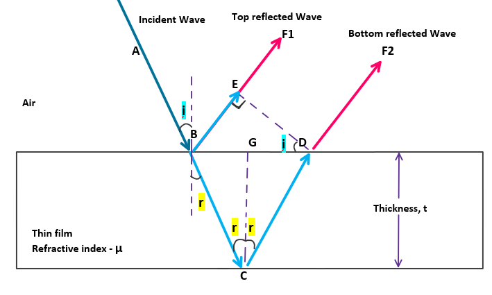
Condition for maximum
To obtain maximum at a point, optical path difference between top and bottom reflected wave should be integer multiple of wavelength. $$opd=n\;\lambda$$ Substituting expression for opd from equation(7), $$ 2\mu t \;cos\;r+\frac{\lambda}{2}=n\;\lambda $$ Rearranging, Condition for obtaining maximum on a thin film of thickness t is given by, $$\boxed{ 2\mu t \;cos\;r = (2n-1)\;\frac{\lambda}{2}}$$Condition for minimum
To obtain minimum ordarkness at a point, optical path difference between top and bottom reflected wave should be half integer multiple of wavelength. $$opd=(2n-1)\;\frac{\lambda}{2}$$ Substituting expression for opd from equation(7), $$ 2\mu t \;cos\;r+\frac{\lambda}{2}=(2n-1)\;\frac{\lambda}{2} $$ Rearranging, Condition for obtaining maximum on a thin film of thickness t is given by, $$\boxed{ 2\mu t \;cos\;r = n\lambda}$$Cosine law
The condition of minimum or darkness in a reflecting system or thin film is called cosine law. $$\boxed{2 \mu t \;cos\;r=n \lambda}$$ where,- \( \mu \) is the refractive index of film
- \( t \) is the thickness of film
- \( r \) is the angle of refraction
- \( \lambda \) is wavelength of light
- n = 1,2,3...
Colours in thin film
According to cosine law, light of wavelength \( \lambda \) will get cancelled or destructively interfere if the thin film obeys the condition,
$$\boxed{2 \mu t \;cos\;r=n \lambda}$$ We know that whitelight contain all the wavelengths of visible spectrum. When white light is incident on a thin film, based on thickness and angle of incidence/refraction some color ( say red) will get minimum or interfere destructively. So that part of film appears to have remaining part of white light (violet or blue).So based on thickness variation and angle of observation, a thin film incident with white light appears colored. This effect is commonly observed in soap bubbles, peacock feathers, oil slicks, and many other natural and man-made surfaces.
Air Wedge
An air wedge is a thin layer of air between two transparent surfaces, which can cause interference patterns due to the difference in refractive index.
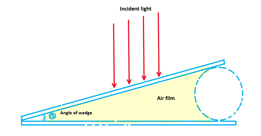
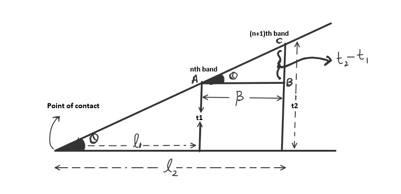
Where θ is the wedge angle and λ is the wavelength of the light used.
If a medium of refractive index \( \mu \) is filled rather than air, then bandwidth is given by, $$\boxed{\;\;\beta = \frac{\lambda}{2\;\mu\;\theta}\;\;}$$Applications of Air wedge
Air wedge is an experimental apparatus in following applications.Diameter of thin wire
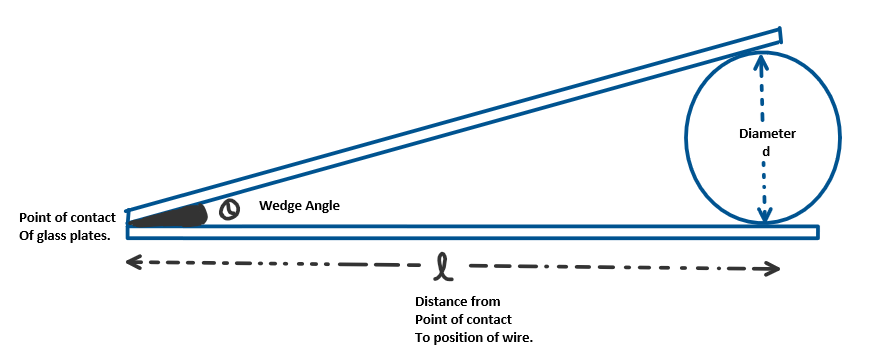
$$\boxed{\;\;\;d = \frac{l \lambda}{2 \beta}\;\;\;}$$
Where:
d is the thickness or diameter of the wire
λ is the wavelength of the light used
\( \beta \) is the bandwidth of interference pattern
Optical planeness of glass plates
Air wedges can also be used to check the optical planeness of a surface. By measuring the angular position of the maxima and minima, it is possible to determine the uniformity of the air gap between the surface and the transparent surface. Any variations in the thickness of the air gap will result in variations in the angular position of the maxima and minima, indicating that the surface is not optically plane.
Newton's Rings
Newton's rings are a pattern of concentric circles formed by the interference of light reflecting off the front and back surfaces of a spherical lens. The phenomenon was first observed and described by Sir Isaac Newton in his book "Opticks" in 1704.
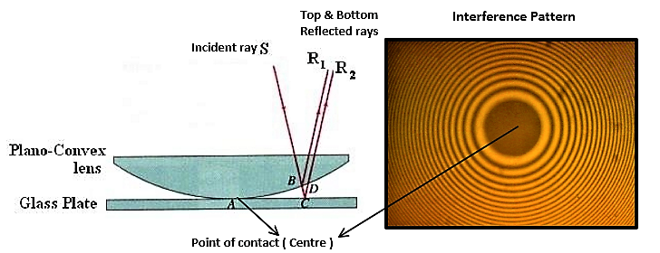
When a plano-convex lens is placed on a flat surface (or glass plate) a thin air film will be formed between lens and glassplate. If this is illuminated with monochromatic light, the light reflecting from top and bottom part of this film interfere with each other. This interference will result in a pattern of bright and dark rings, with the center of the pattern being the point of contact between the lens and the flat surface.
Radius of nth dark ring
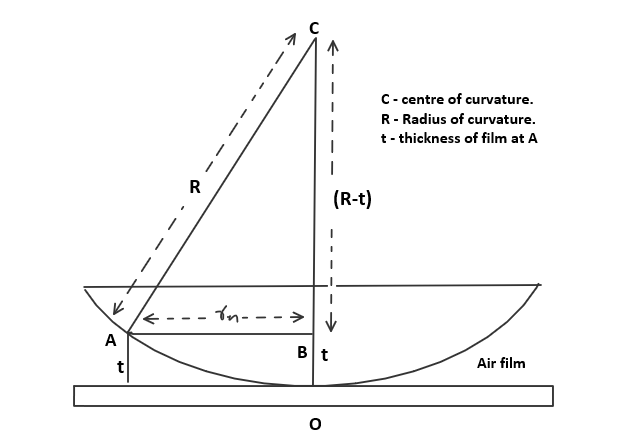
Where R is the radius of curvature of the lens and λ is the wavelength of the light used.
Applications of newton's rings
Newton's rings can be used to ,Calculation of wavelength
Radius of nth dark ring is given as, $$ r_n = \sqrt{Rn \lambda} $$ So the diameter of nth dark ring \( D_n \) is given by [ \( diameter = 2 \times radius \)], $$ D_n = 2 \sqrt{Rn \lambda} $$ squaring both sides, $$D_n^2 = 4Rn \lambda -->eqn(3)$$ Diameter of (n+k)th dark ring is given by, $$D_{n+k}^2 = 4R(n+k) \lambda -->eqn(4)$$ Subracting equation(3) from equation(4), $$D_{n+k}^2 - D_n^2 = 4R(n+k) \lambda - 4Rn \lambda $$ $$D_{n+k}^2 - D_n^2 = 4Rk \lambda-->eqn(5)$$ Or wavelength can be calculated as, $$\boxed{\;\lambda = \frac{D_{n+k}^2 - D_n^2}{4Rk}\;}$$where \( D_{n+k} \) is the diameter of (n+k) th ring and \( D_{n} \) is diameter of nth dark ring. R is the radius of curvature of lens used in this experiment.
Calculation of refractive index
If the gap between plano convex lens and glass plate is filled with any liquid of refractive index \( \mu \), radius of nth dark ring can be modified as, $$r_n^2 = \frac{R n \lambda}{\mu} $$ So diameter of nth ring and (n+k)th ring will be , $$d_n^2 = \frac{4Rn \lambda}{\mu}$$ $$d_{n+k}^2 = \frac{4R(n+k) \lambda}{\mu}$$ Subracting each other, $$d_{n+k}^2 - d_n^2 = \frac{4Rk \lambda}{\mu} -->eqn(6)$$ Dividing equation(5) with equation(6), We get the refractive index of liquid as, $$\boxed{\;\mu = \frac{D_{n+k}^2 - D_n^2}{d_{n+k}^2 - d_n^2}\;}$$ where \(D_n \) and \( D_{n+k} \) are diameters of nth and (n+k)th dark ring when air is between glass plate and lens. \( d_n \) and \( d_{n+k} \) are diameters of nth and (n+k)th dark rings when liquid of refractive index \( \mu \) is introduced between lens and plate.Anti-Reflection Coating
Anti-reflection coatings are thin films applied to surfaces to reduce the amount of reflection that occurs. They work by introducing a thin layer of material with a lower refractive index than the surface it is applied to. This creates a difference in the phase of the light waves reflecting off the surface and the coating, which results in constructive and destructive interference, reducing the overall amount of reflected light.
Anti-reflection coatings are commonly used on lenses, mirrors, and other optical surfaces to improve transmission and reduce glare.
Interference Filters
Interference filters are optical devices that use the principle of constructive and destructive interference to selectively pass certain wavelengths of light while blocking others. They consist of multiple thin film layers with varying refractive indices, which cause the different wavelengths of light to experience different amounts of phase shift, resulting in selective transmission or reflection.
Interference filters are used in a variety of applications, including spectroscopy, imaging, and color separation.